CARBURETOR REMOVAL
Before removing the carb download the service manual for pictures, illustrations and diagrams for assistance with these procedures. Procedures differ between all years and models and the following should not be used as an exact guide.
To remove the carburetor start by removing the side covers and air cleaner housing. Place and approved fuel container under the drain tube. Then loosen the drain screw and drain the carburetor. Then release the carburetor heater wire from the clip and disconnect its connector if equipped. Disconnect the fuel tube and loosen the starting enrichment (SE) valve nut.
Remove the screw and the throttle drum cover and loosen the insulator band screw to remove the carburetor off the insulator. Disconnect the choke cable by turning the SE
valve nut, being careful not to damage the SE valve. Loosen the throttle cable lock nut and remove the adjuster from the carburetor body, and disconnect the cable from the throttle drum. Now you can remove the carburetor.
CARBURETOR DISASSEMBLY/INSPECTION
Start by inspecting the following:
Check the SE valve face for scores, scratches or wear.
Check the SE valve seat at the tip of the valve for stepped wear.
Check the seal ring for wear or damage.
Start by removing the following from the carburetor body:
air vent tubes
drain tubes
carburetor heater
AIR CUT-OFF VALVE
Remove the attaching screw and the air cut-off valve and then remove the O-rings and joint pipe. Apply vacuum to the vacuum tube and the vacuum should be maintained. Air should not flow through the valve ports when the vacuum is applied, and should flow when the vacuum is not applied.
VACUUM CHAMBER
Remove the four screws with the tube clamp and the vacuum chamber cover while holding it. Remove the compression spring and diaphragm/vacuum piston from the carburetor body and turn the needle holder counterclockwise by using a screwdriver while pressing it in and release the holder flange from the vacuum piston. Then remove the needle holder, spring, jet needle and washer.
Inspect the following:
Check the jet needle for stepped wear.
Check the vacuum piston for wear or damage.
Check the diaphragm for pin hole, deterioration or damage.
Check the vacuum piston for smooth operation up and down in the carburetor body.
Air will leak out of the vacuum chamber if the diaphragm is damaged in any way, even with just a pin hole.
PRIMER KNOB
Remove the two screws while holding the primer knob body and then remove the primer knob assembly and spring. Inspect the diaphragm for pin holes, deterioration or damage.
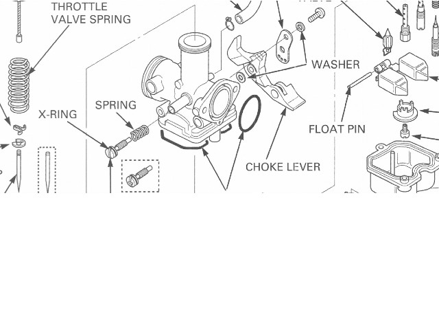
FLOAT CHAMBER
Remove the four screws and the float chamber and then remove the following:
baffle plate
float pin
float
float valve
Inspect the following components:
Check the float for damage or fuel in the float.
Check the float valve and valve seat for scoring, scratches, clogging or damage.
Check the tip of the float valve, where it contacts the valve seat, for stepped wear or contamination.
Check the operation of the float valve.
Remove the following:
main jet
needle jet holder
needle jet
slow jet
starter jet
rubber plug
Turn the pilot screw in and carefully count the number of turns until it seats lightly. Make a note of this to use as a reference when reinstalling the pilot screw and then remove the pilot screw, spring, washer and O-ring.
Check each jet for wear or damage.
Check the pilot screw for wear or damage.
Clean the jets with cleaning solvent and blow open with compressed air.
CARBURETOR CLEANING
Start by removing the following parts:
air cut-off valve
diaphragm/vacuum piston.
main jet, needle jet holder and needle jet
slow jet
starter jet
pilot screw
Blow open all air and fuel passages in the carburetor body with compressed air.
FLOAT AND JETS
Install the pilot screw with the spring, washer and a new O-ring and return it to its original position as noted during removal. Perform the pilot screw adjustment if a new pilot screw is installed.
Install the following:
needle jet
needle jet holder
main jet
slow jet
starter jet
rubber plug
Hang the float valve onto the float arm lip and the install the float valve and float. The next step is to install the float pin as shown in the service manual picture illustration. Lastly install the baffle plate.
FLOAT LEVEL INSPECTION
NOTE: Check the float level after checking the float valve, valve seat and float.
With the float valve seated and the float arm just touching the valve, measure the float level with the float level gauge. The float cannot be adjusted. Replace the float assembly if the float level is out of specification (see service manual for spec's). Install the baffle plate by aligning its groove with the lug on the carburetor body as shown in your service repair manual. Install a new O-ring into the float chamber groove securely. Install the float chamber and tighten the four screws.
PRIMER KNOB
Install the primer knob with the spring and tighten the two screws, being careful not to pinch the diaphragm.
VACUUM CHAMBER
Install the needle clip onto the jet needle and the washer onto the jet needle and insert the jet needle into the vacuum piston. Install the spring into the needle holder and set the needle holder into the vacuum piston. Turn the needle holder clockwise while pressing it until it locks. Holder flange should be fitted the vacuum piston after turning.
Install the diaphragm/vacuum piston into the carburetor body by aligning the tab of the diaphragm with the air passage, then insert the jet needle into the needle jet. Lift the bottom of the piston with your finger to set the diaphragm rib into the groove in the carburetor body.
Install the spring and vacuum chamber cover while the piston remains held in place. Align the concave of the cover with the air passage in the carburetor and secure the cover with at least two screws before releasing the vacuum piston. Install the screws with the tube clamp and tighten them.
AIR CUT-OFF VALVE
Install new O-rings onto the air cut-off valve and joint pipe. Install the joint pipe into the air cut-off valve with the stepped side facing the air cut-off valve. Install the air cut-off valve and secure it with the screw. Turn the throttle stop screw to align the butterfly throttle valve with the edge of the outside by-pass hole in the carburetor body, If the throttle stop screw was removed. Install the collar and carburetor heater with the stepped side of the collar facing the carburetor and tighten it. Install the following tubes to the carburetor and secure the air vent tube with the clamp as shown: air cut-off valve vacuum tube air vent tubes drain tube.
CARBURETOR INSTALLATION
Connect the throttle cable to the throttle drum and install the cable adjuster into the carburetor body. Connect the choke cable by screwing the SE valve nut, being careful not to damage the SE valve. Install the carburetor into the insulator by aligning the lug with the groove, and tighten the band screw. Tighten the SE valve nut and connect the fuel tube.Now install the throttle drum cover by aligning its tab with the slit in the carburetor and secure it with the screw. Route the tubes and wire properly and connect the carburetor heater connector (See diagram in your service manual).
Continue by removing the following parts:
air cleaner housing
side covers
Perform the following inspections and adjustments. Engine idle speed (refer to your service manual) and throttle operation (refer to your service manual). Adjust the pilot screw if it was replaced.
PILOT SCREW ADJUSTMENT
IDLE DROP PROCEDURE
NOTE: The pilot screw is factory pre-set and no adjustment is necessary unless the pilot screw is replaced. Use a tachometer with graduations of 50 rpm or smaller that will accurately indicate a 50 rpm change. Turn the pilot screw clockwise until it seats lightly, then back it out to the specification given. This is an initial setting prior to the final pilot screw adjustment. Warm up the engine to operating temperature.
Stop and go riding for 10 minutes is sufficient. Stop the engine and connect a tachometer according to the tachometer manufacturer’s instructions. Start the engine and adjust the idle speed with the throttle stop screw. Turn the pilot screw in or out slowly to obtain the highest engine speed.
Lightly open the throttle 2 3 times, then adjust the idle speed with the throttle stop screw. Turn the pilot screw in gradually until the engine speed drops by 100 rpm. Turn the pilot screw out to the final opening. Readjust the idle speed with the throttle stop screw.
HIGH ALTITUDE ADJUSTMENT
The carburetor must be adjusted for high altitude riding (between 3,000 8,000 ft/1,000 2,500 m).
STANDARD SETTING: Below 5,000 ft (1,500 m)
HIGH ALTITUDE SETTING: Between 3,000 8,000 ft (1,000 2,500 m)
The high altitude carburetor adjustment is performed as follows:
Remove the carburetor (see diagram in your manual) and the float chamber. Replace the standard main jet with the high altitude
type.
HIGH ALTITUDE MAIN JET: # 125
Check that the O-ring on the float chamber is in good condition and replace it with a new one if necessary. Install the float chamber and the carburetor. Turn-in the pilot screw the specified number of turns from the initial setting.
HIGH ALTITUDE PILOT SCREW OPENING:
3/4 turn in from initial opening
Start the engine and adjust the idle speed at high altitude to ensure proper high altitude operation. Sustained operation below 5,000 ft (1,500 m) with the high altitude settings may cause engine overheating and engine damage. Install the standard main jet and screw out the pilot screw the specified number of turns, when riding below 5,000 ft (1,500 m.
STANDARD MAIN JET: # 130
Pilot screw change for low altitude: 3/4 turn out.