1984-2007 Honda CR80R/CR85R/CR125R/CR250R Cylinder/Piston Overhaul
CR80/CR85/CR125/CR250-R Cylinder & Piston |
|
Always refer to a service manual before attempting to do any work on your motorcycle, important data including step-by-step procedures, diagrams, pictures, illistrations, specifications cleaning & maintenance information will help you care for and lower the chances of premature parts failurer. Below is a great reference source available for instant download straight to your computers in just seconds.
1
All manuals are simple to use pdf downloads and are delivered straight to your computer in just seconds. Not sure what a pdf is? Here is a sample of what a Service Manual looks like (sample is restricted to one page only).
1
Service Manuals
HONDA CR125/CR125R
1
MODEL/YEAR APPLICATION:
Honda CR125R, CR125-R, CR-125-R, CR125 1984, 1985, 1986, 1987, 1988, 1989, 1990, 1991, 1992, 1993, 1994, 1995, 1996, 1997, 1998, 1999, 2000, 2001, 2002, 2003, 2004, 2005, 2006 & 2007 models.
Honda CR250R, CR250, CR-250R, CR250-R 85, 86, 87, 88, 89, 90, 91, 92, 93, 94, 95, 96, 97, 98, 99, 00, 01, 02, 03, 04, 05, 06 & 07 year CR250R models.
Honda CR80R, CR85R, CR80, CR85, CR-80-R, CR-85-R 1984, 85, 86, 87, 88, 89, 90, 91, 92, 93, 94, 95, 96, 97, 98, 99, 00, 01, 02, 03, 04, 05, 06 & 07 year CR-80/85-R models.
|
This cylinder-piston guide describes the service procedures as general procedures and what is involved in the replacement, service and overhaul of top end piston & cylinder on Honda CR80R / CR85R / CR125R & CR250R motorcycles. It is only recommended to follow the cylinder & piston guide in the reference guide links listed above as they contain the same information mechanics and technicians use to service your bike.
Important information contained in this page like special notes, tips, proper procedures, complete specifications, torque specs, additional torque specs and recommendations must be followed in the reference links to ensure that the task is performed in the proper flow and to manufacture spec's recommendations.
|
The piston & cylinder can be serviced with the engine installed in the frame. Take care not to damage the cylinder wall and piston. Be careful not to damage the mating surfaces when removing the cylinder. Do not strike the cylinder too hard during removal.
TROUBLESHOOTING
When might it be time to service and overhaul the piston and cylinder? The following is a list of troubleshooting areas that should be performed to dianosis the causes.
Troubleshooting and possible causes:
- Leaking cylinder head gasket
- Worn, stuck or broken piston ring
- Worn or damaged cylinder and piston
- Bent connecting rod
- Excessive carbon built-up on piston head or combustion chamber
- Worn cylinder, piston or piston rings
- Improper installation of piston rings
- Scored or scratched piston or cylinder wall
- Worn piston pin or piston pin hole
- Worn connecting rod small end
- Worn cylinder, piston or piston rings
|
CYLINDER/PISTON REMOVAL
CYLINDER REMOVAL
Remove the cylinder head (see diagrams in reference download) and remove the following:
Cylinder
Gasket
Dowel pins
Do not strike the cylinder too hard and do not damage the mating surface with a screwdriver.
PISTON REMOVAL
Place a clean shop towel over the crankcase to prevent the clip from falling into the crankcase then remove the piston pin clips with pliers. Push the piston pin out of the piston and connecting rod, and remove the piston. Spread each piston ring and remove it by lifting up at a point opposite the gap. Clean carbon deposits from the ring grooves with a ring that will be discarded. Never use a wire brush; it will scratch the groove.
INSPECTION
CYLINDER
Inspect the cylinder bore for scratch(s) or wear. Measure the cylinder I.D. at three levels in an X and Y axis. Take the maximum reading to determine the cylinder wear (see reference download for service limits for exact model and year).
SERVICE LIMIT: Always refer to the reference links above for service wear limits.
Calculate the cylinder-to-piston clearance. Refer to your manual download for measurement of the piston O. Calculate the cylinder taper and out-of-round at three levels in an X and Y axis. Take the maximum reading to determine the taper and out-of-round. The cylinder must be rebored and an oversize piston fitted if the service limits are exceeded. The four oversize pistons are available from 0.25 mm piston to 1.0 mm piston in intervals of 0.25 mm (0.010 in).
The cylinder must be rebored so that the clearance for an oversize piston is (see reference links) mm (see reference links). Check the top of the cylinder for warpage with a straight edge and feeler gauge across the studs and bolt holes.
PISTON/PISTON RING
Inspect the piston rings for movement by rotating the rings. The rings should be able to move in their grooves without catching. Push the ring until the outer surface of the piston ring is nearly flush with the piston and measure the ring-to-ring groove clearance. Insert each piston ring into the bottom of the cylinder squarely using the piston. Measure the ring end gap. Measure the piston pin O.D. 90° to the piston pin hole and at point 15 mm (0.6 in) from bottom of the piston skirt. Compare this measurement against the maximum cylinder I.D. measurement and calculate the piston-to- cylinder clearance.
Measure piston pin hole and take the maximum reading to determine the I.D. Measure the piston pin O.D. at three points and calculate the piston-to-piston pin clearance. Measure the connecting rod small end I.D. Calculate the connecting rod-to-piston pin clearance.
CYLINDER STUD BOLT REPLACEMENT
Remove the stud bolts from the cylinder and install new stud bolts in their proper positions and tighten them. After installation, measure the stud height from the cylinder surface.
CYLINDER/PISTON INSTALLATION
PISTON RING INSTALLATION
Carefully install the piston rings into the piston ring grooves with the markings facing up.
NOTE: Do not confuse the top and second rings. To install the oil ring, install the spacer first, then install the side rails. Stagger the piston ring end gaps 120° degrees apart from each other. Stagger the side rail end gaps as shown. Be careful not to damage the piston and rings.
OIL RINGS
SPACER
SECOND RING
TOP RING
PISTON INSTALLATION
Place a clean shop towel over the crankcase to prevent the clip from falling into the crankcase. Apply molybdenum oil solution to the piston pin outer surface. Apply engine oil to the piston pin hole and connecting rod inner surface. Install the piston with the ‘‘IN’’ mark toward the intake side and insert the piston pin through the piston and connecting rod. Install new piston pin clips into the grooves in the piston pin hole. Make sure that the piston pin clips are seated securely. Do not align the piston pin clip end gap with the piston cutout.
CYLINDER INSTALLATION
Clean the gasket surfaces of the cylinder and crankcase thoroughly, being careful not to damage it, and being careful not to allow gasket material into the crankcase. Blow through the oil passage (stud bolt hole) in the cylinder with compressed air. Apply liquid sealant to the crankcase mating areas. Install the dowel pins and a new gasket and apply engine oil to the cylinder wall, piston and piston ring outer surfaces. Install the cylinder over the piston while compressing the piston rings with your fingers. Make sure that the cylinder touches the crankcase evenly. Install the cylinder head (see diagrams in reference download). |
Similar Honda Piston CR80R (CR80) CR85R (CR85) CR125R (CR125) CR250R (CR250) Searches:
- 03 cr250r piston selection
- piston seized on dirt bike cr80r 1985 85
- piston replacement 02 cr250r
- 04 cr250 racing piston
- lost compression CR250R
- Fixing the CR250 Piston slap
- 98 CR250R Top End Rebuild Questions
- Honda Cr250r Cr250 92-96 Piston Kit
- Honda CR250 pistons CR 250 piston kits
- CR250 gasket kits
- Honda CR 125 Piston Kits
- Where to buy Piston replacement cr85r 1996
- 01 CR125 top end rebuild
- 98 1998 CR250R Top End Rebuild Questions
- How do you install piston and ring honda 94 cr 125
- How can you change the piston ring in a Honda dirtbike 250cc
- 01 cr125 piston and rings
- Cr125r 2001 01 cant start after changing piston
- Top end piston and ring replacement
- 1985 85 honda cr125 change the bearing on the piston rod
- Honda CR125 Tech Tips
- PISTON RING 49.5MM pin
- How to change Honda Cr125 Piston rings
|
PISTON RING INSTALLATION
NOTE:
ring lands. Always check piston ring installed gap
before rings are installed on piston. See Page 3.36.
If the piston has been in service clean any
accumulated carbon from the ring grooves and oil
control ring holes.
1. Place the oil control ring expander in oil ring
groove with the end gap facing forward. The
expander has no up or down marking and can be
installed either way. The ends should butt
squarely together and must not overlap.
2. Install the oil ring top rail with the end gap at least
30
3. Install the bottom rail with the gap at least 30
from the end of the expander on the side opposite
the top rail gap.
Ring Profile
Top
“R1” Mark up
“R” Mark up
Second
4. Install the second ring with the “R”mark facing up.
Position the end gap toward the rear (intake) side
of the piston.
5. Install the top ring (chrome faced) with the “R1”
mark facing up and the end gap facing forward
(toward the exhaust).
6. Check to make sure the rings rotate freely in the
groove when compressed.
Apply clean engine oil to all ring surfaces and from the end of the expander.
PISTON INSTALLATION
1. Clean the gasket surfaces on the cylinder and
crankcase. Remove all traces of old gasket
material.
2. Make sure the cylinder mounting bolt holes are
clean and free of debris.
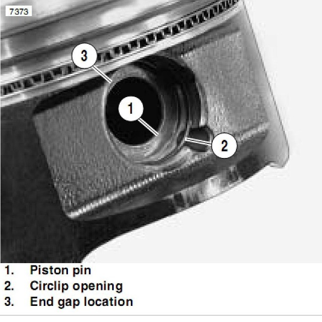
3. Install a new circlip on one side of the piston with
the end gap facing
up or down.
CAUTION:
removal process. Do not re-use old circlips. Do not
compress the new clip more than necessary upon
installation to prevent loss of radial tension. Severe
engine damage may result if circlips are re-used or
deformed during installation.
Circlips become deformed during the |
4. Apply clean engine oil to the piston rings, ring
lands, piston pin bore, piston pin, and piston skirt.
Lubricate the connecting rod (both ends) and
crankshaft main bearing area.
5. I
the pin casting notch facing the rear of engine
(starter side). The piston pin should be a
push fit in the piston.
nstall the piston on the connecting rod with
6. Install the other circlip with the gap facing up or
down. (See Caution withStep 3 above). Push the
piston pin in both directions tomake sure the clips
are properly seated in the groove.
7. Place the dowel pins in the crankcase and install a
new cylinder base gasket.
8. Lubricate the piston and rings with assembly lube
and install a sleeve--type ring compressor on the
piston assembly. Verify that the ring gaps are 120
degrees apart from each other before installation.
CYLINDER INSTALLATION
1. Position the Piston Support Block (
(A) beneath the piston skirt to support the piston
during cylinder installation.
A
2. Apply clean engine oil liberally to the cylinder bore
and tapered area of the sleeve. Install the
cylinder with a slight rocking motion until the rings
are captive in the sleeve.
3. Remove the ring compressor and support block.
4. Push the cylinder downward until fully seated on
the base gasket.
PN 2870390)
NOTE:
rotating the engine to avoid damage to the chain, drive
sprocket teeth, or tensioner blade.
5. Install the two 6 mm bolts, but do not tighten.
If cam chain is installed, hold it up while
CYLINDER HEAD
INSTALLATION
Clean the gasket surfaces on the cylinder head and
cylinder. Remove all traces of old gasket material.
1. Install the cam chain tensioner guide. Be sure
bottom end of guide is located properly in
crankcase.
2. Install the two dowel pins and a new cylinder head
gasket.
3. Place the cylinder head on the cylinder. Apply a
film of engine oil to the cylinder head bolt threads
and washers, and hand tighten the bolts.
|
|
|