1991-2009 Strut, Struts, Shocks, Springs, Coilovers (Coil-Overs) Replacement, Installation, Removal, Repair, Service Specification, Diagrams & Troubleshooting Guide for 1991, 1992, 1993, 1994, 1995, 1996, 1997, 1998, 1999, 2000, 2001, 2002, 2003, 2004, 2005, 2006, 2007 & 2009 Accord/Coupe Models. DOWNLOAD!
1991-2009 Honda Accord Strut, Struts, Front Struts, Shocks, Spring & Coilovers (Coil-Overs)
1 |
|
Instantly download Honda Accord service manuals below
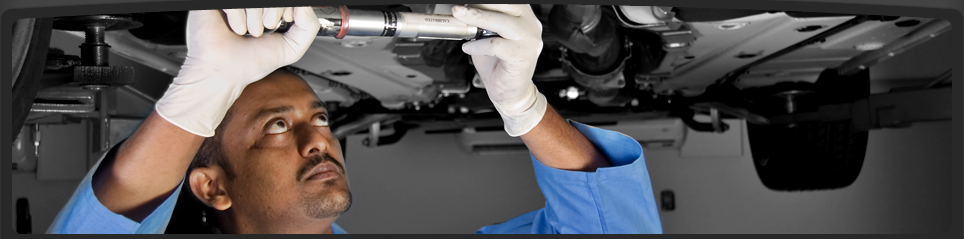
Choose a service manual from the list below and download it straight to your computer in just seconds! These manuals contain the same exact information Honda service technicians use to service and repair your automobile.
All manuals contain pictures, illustrations, diagrams, specifications, special tools, solvents & step-by-step procedures and much more!
These Factory Service Manuals contain everything you will ever need to know to fix anything on your honda accord. Want to see a sample of what a honda service manual looks like?
SAMPLE MANUAL
(Sample manual restricted to one page)
COMPLETE SERVICE MANUAL
DOWNLOAD LINKS BELOW
|
|
Select a manual above for download, these are original factory service manuals available for download straight to your computer in just seconds! Stop the guess work and get a repair manual.
Yes, these manuals conatin pictures, diagrams, illistrations and step-by-step procedures to make your repair work a breeze, no special software required on your computer, just download and go.
1991-1993 Models covered in this Honda Accord Shop Manual: 1991, 1992 and 1993 Honda Accord, 1991, 1992, 1993 Honda Accord Aero Deck and 1992 Honda Accord Coupe. Engines Covered in this manual are: F18A F20A F22A
1994-1997 Service Manual Model/Year Applications: Honda Accord Coupe 2 Door: 1994, 1995, 1996, 1997 DX, LX, EX, ES, LS, iES, iLS, Engine Type: F22B1 2.2 SOHC (VTEC) Sequential Multi-Port Fuel Injected engine. Egnine Type: F22B2 2.2 -F20B3 2.0 - F22B5 2.2 SOHC Sequential Multi-Port Fuel Injected Engine VTEC & Non VTEC.
1998-2002 Honda Accord EX, LX, DX, LX V6, EX V6 Models with 2.3L 150 hp I4 & 3.0L 200 hp V6 engines
2003-2007 Honda Accord Service Manual Application: This Manual Covers all 2003-2007 Honda Accord USA & Canada Models 2003, 2004, 2005, 2006, 2007, Honda Accord LX, EX, DX, 2.4L & 3.0L 4 & 6 cylinder models, 2.4L 160 hp, 3.0L 240 hp.
1
2008-2009 Exact Models Covered In This Service Manual: (THIS MANUAL COVERS ALL 2008-2009 HONDA ACCORDS and COUPE), 2008 4 Door Model (Accord), 2008 2 Door Model (Accord Coupe / K24Z3), 2009 Accord / K24Z2, K24Z3, 2008 08' 4 Door Sedan 5 Speed Manual, 2008 08' 4 Door Sedan 5 Speed Automatic, 2008 2 Door Coupe/5-Speed Manual, 2008 2 Door Coupe/5-Speed Manual, 2009 09' 4-2 Door Sedan 5 Speed Manual, 2009 09' 4-2 Door Sedan 5 Speed Automatic, 2009 09' 4-2 Door Honda Accord Coupe/K24-Z3, LX (L X), EX (E X), EX-L models.
2008-2009 Honda Engines Covered: 2008 K24, K-24, K24Z2, 2.4L DOHC i-VTEC Sequential Multiport Fuel Injected, 177HP Engine, 2008 K24, K-24, K24Z3, 2.4L DOHC i-VTEC Sequential Multiport Fuel Injected, 190HP Engine, 2008 K24, K-24, K24A3, 2.4L DOHC i-VTEC Sequential Multiport Fuel Injected, 190HP Engine, 2009 K24, K-24, K24Z2, 2.4L DOHC i-VTEC Sequential Multiport Fuel Injected, 177HP Engine, 2009 K24, K-24, K24Z3, 2.4L DOHC i-VTEC Sequential Multiport Fuel Injected, 190HP Engine, 88E5 - 5-Speed Manual, M91A - 5 Speed Automatic, B90A - 5 Speed Automatic.
|
|
STRUT ASSEMBLY
DESCRIPTION - STRUT ASSEMBLY (FRONT)
A Macpherson type design strut assembly is used in place of the front suspension upper control arm and upper ball joint (Fig. 1). The bottom of the strut mounts directly to the steering knuckle using 2 attaching bolts and nuts going through the strut clevis bracket and steering knuckle. The top of the strut mounts directly to the strut tower of the vehicle using the three threaded studs on the strut assemblies upper mount. During steering maneuvers, the strut assembly (through a pivot bearing in the upper strut mount) and steering knuckle (through the lower ball joint) turn as an assembly.
The strut assembly includes the following components:
² Strut shaft retaining nut
² Upper mount (rubber isolated)
² Upper spring seat and bearing
² Dust shield
² Jounce bumper
² Coil spring
² Lower spring isolator
² Strut (damper)
Each component is serviced by removing the strut assembly from the vehicle and disassembling it. The strut and front suspension of the vehicle is supported by coil springs positioned around the
upper half of each strut. The springs are contained between the upper and the lower seats of the strut assembly.
Coil springs are rated separately for each corner or side of the vehicle depending on optional equipment and type of vehicle service. During service procedures of the strut assembly, if both springs are removed mark the springs to ensure installation in its original position.
NOTE: If a coil spring requires replacement, be sure that it is replaced with a spring meeting the correct load rating for the vehicle and its specific options.
OPERATION - STRUT ASSEMBLY (FRONT) The strut assembly cushions the ride of the vehicle, controlling vibration, jounce and rebound of the suspension. The coil spring controls ride quality and maintains proper ride height. The spring isolators isolate the coil spring at the top and bottom from coming into metal-to-metal contact with the upper mounting seat and the strut. The jounce bumper limits suspension travel and metal-to-metal contact under full jounce condition. The strut dampens jounce and rebound motions of the coil spring and suspension.
DIAGNOSIS AND TESTING - STRUT ASSEMBLY (FRONT)
Inspect the strut assembly for the following conditions (Fig. 54):
² Inspect for a damaged or broken coil spring.
² Inspect for a torn or damaged strut assembly dust shield.
² Lift the dust shield and inspect the strut assembly for evidence of fluid running from the upper end of the strut fluid reservoir. (Actual leakage will be a stream of fluid running down the side and dripping off lower end of unit). A slight amount of seepage between the strut shaft and strut shaft seal is not unusual and does not affect performance of the strut assembly.
² Lift the dust shield and inspect the jounce bumper for signs of damage or deterioration
² Inspect the clearance between the shock tower and the coil spring. Make sure no fasteners are protruding through the shock tower possibly contacting the coil spring and strut. Because of the minimum clearance in this area (Fig. 55), installation of metal fasteners could damage the coil spring coating and lead to a corrosion failure of the spring.
CAUTION: At no time when servicing a vehicle can a sheet metal screw, bolt or other metal fastener be installed into the shock tower to take the place of an original plastic clip. Also, do not drill holes into the front shock tower for the installation of any metal fasteners into the shock tower area indicated (Fig. 55).
REMOVAL - STRUT ASSEMBLY (FRONT)
NOTE: Before proceeding with this procedure, (Refer to 2 - SUSPENSION/FRONT - WARNING).
(1) Raise the vehicle. (Refer to LUBRICATION & MAINTENANCE/HOISTING - STANDARD PROCEDURE).
(2) Remove tire and wheel assembly from location on front of vehicle requiring strut removal. (Refer to 22 - TIRES/WHEELS - REMOVAL)
(3) If both strut assemblies are to be removed, mark the strut assemblies right or left according to which side of the vehicle they were removed from.
(4) Remove the screw securing the ground strap to the rear of the strut (Fig. 56).
(5) If the vehicle is equipped with Antilock brakes (ABS), remove the screw securing the ABS wheel speed sensor to the rear of the strut (Fig. 56).
1 - NUT
2 - STRUT ASSEMBLY
3 - STRUT
4 - LOWER SPRING ISOLATOR
5 - COIL SPRING
6 - JOUNCE BUMPER
7 - DUST SHIELD
8 - SPRING SEAT AND BEARING (WITH SPRING ISOLATOR)
9 - UPPER MOUNT
1 - SHOCK TOWER
2 - COIL SPRING
3 - NO SHEET METAL SCREWS, BOLTS, OR ANY OTHER METAL FASTENERS ARE TO BE INSTALLED INTO SHOCK TOWER IN THIS AREA. ALSO, NO HOLES ARE TO BE DRILLED INTO
SHOCK TOWER IN THIS SAME AREA.
1 - ABS WHEEL SPEED SENSOR ROUTING BRACKET (IF EQUIPPED)
2 - GROUND STRAP
3 - GROUND STRAP SCREW
4 - ABS SENSOR BRACKET SCREW (IF EQUIPPED)
CAUTION: The strut assembly-to-steering knuckle attaching bolts are serrated and must not be turned during removal. Hold the bolts stationary in the steering knuckle while removing the nuts, then tap the bolts out using a pin punch.
(6) Remove the two bolts attaching the strut to the steering knuckle (Fig. 1).
(7) Lower the vehicle just enough to open the hood, but without letting the tires touch the floor.
(8) Remove the three nuts attaching the upper mount of the strut assembly to the vehicle’s strut tower (Fig. 57).
(9) Remove the strut assembly from the vehicle.
(10) For disassembly procedures, (Refer to 2 - SUSPENSION/FRONT/STRUT - DISASSEMBLY).
DISASSEMBLY - STRUT ASSEMBLY (FRONT)
The Strut assembly must be removed from the vehicle for it to be disassembled and assembled. (Refer to 2 - SUSPENSION/FRONT/STRUT - REMOVAL). For the disassembly and assembly of the strut assembly, use strut spring compressor, Pentastar Service Equipment (PSE) tool W-7200, or the equivalent, to compress the coil spring. Follow the manufacturer’s instructions closely.
(1) If both struts are being serviced at the same time, mark the coil spring and strut assembly according to which side of the vehicle the strut was removed from, and which strut the coil spring was
removed from.
(2) Position the strut assembly in the strut coil spring compressor following the manufacturers instructions. Set the lower hooks (Fig. 58), then set the upper hooks (Fig. 59). Position the strut clevis
bracket straight outward away from the compressor. Place a clamp on the lower end of the coil spring, so the strut is held in place once the strut shaft nut is removed (Fig. 58).
WARNING: DO NOT REMOVE THE STRUT SHAFT NUT BEFORE THE COIL SPRING IS COMPRESSED. THE COIL SPRING IS HELD UNDER PRESSURE AND MUST BE COMPRESSED, REMOVING SPRING TENSION FROM THE UPPER MOUNT AND PIVOT BEARING, BEFORE THE SHAFT NUT IS REMOVED.
(3) Compress the coil spring until all coil spring tension is removed from the upper mount.
(4) Once the spring is sufficiently compressed, install Strut Nut Socket, Special Tool 6864, on the strut shaft retaining nut (Fig. 60). Next, install a socket on the hex on the end of the strut shaft. While holding the strut shaft from turning, remove the nut from the strut shaft.
(5) Remove the upper mount from the strut shaft (Fig. 61).
(6) Remove the upper spring seat and bearing, along with the upper spring isolator as an assembly from the top of the coil spring by pulling them straight up (Fig. 61). The upper spring isolator can be separated from the spring seat and bearing once removed from vehicle.
(7) Remove the dust shield, then the jounce bumper from the strut shaft by pulling each straight up (Fig. 61).
(8) Remove the clamp from the bottom of the coil spring and remove the strut out through the bottom of the coil spring.
(9) Remove the lower spring isolator from the lower spring seat on the strut.
NOTE: If the coil spring needs to be serviced, proceed with the next step, otherwise, proceed with step 11.
(10) Release the tension from the coil spring by backing off the compressor drive completely. Push back the compressor hooks and remove the coil spring.
(11) Inspect the strut assembly components for the following and replace as necessary:
² Inspect the strut for any condition of shaft binding over the full stroke of the shaft.
² Inspect the jounce bumper for cracks and signs of deterioration (non-ACR vehicles only).
² Check the upper mount for cracks and distortion and its retaining studs for any sign of damage.
1 - NOTCH IN UPPER SEAT
2 - UPPER MOUNT
3 - UPPER HOOKS
4 - CLEVIS BRACKET
1 - SPRING COMPRESSOR
2 - SPECIAL TOOL 6864
3 - UPPER MOUNT
1 - NUT
2 - STRUT ASSEMBLY
3 - STRUT
4 - LOWER SPRING ISOLATOR
5 - COIL SPRING
6 - JOUNCE BUMPER
7 - DUST SHIELD
8 - SPRING SEAT AND BEARING (WITH SPRING ISOLATOR)
9 - UPPER MOUNT |
Additional Searches for Honda Accord:
90, 1991, 1992, 1993, 1994, 1995, 1996, 1997 HONDA ACCORD FRONT UPPER STRUT BAR TOWER BRACE
1999 HONDA ACCORD Quick Install Strut Assembly FRONT DR
1998-2002 HONDA ACCORD MONROE QUICK STRUT FRONT RIGHT
1998, 1999, 2000, 2001, 2002 Honda Accord Strut/Spring Front Quick Pair
JDM ACCORD GUNMETAL FRONT UPPER STRUT BAR TOWER BRACE
92 Honda Accord FRONT Strut PAIR (Monroe Quick Struts)
99 00 01 02 HONDA ACCORD RH STRUT SHOCK
REAR PAIR STRUTS HONDA ACCORD 1986 1987 1988 1989 NEW
Megan Front Upper Strut Bar Honda Accord 90 - 97 P
New KYB AGX Gas Shocks Struts 1990-1997 Honda Accord
Honda Accord 94-97 DX LX EX Front Rear Strut Brace Bar
1990 1991 1992 1993 Honda Accord Lower Coilover Springs
94-97 HONDA ACCORD RACING COILOVER SPRINGS KIT
94-97 HONDA ACCORD ADJUSTABLE COIL COILOVER SPRING BLUE
D2 RACING COILOVER 90 91 92 93 94 95 96 97 HONDA ACCORD
MEGAN COILOVER DAMPER KIT EZ STREET 90-97 HONDA ACCORD |
1991-2009 Honda Accord Service Manual, Accord Repair Manual, Honda Accord Owner's Service Repair Manual, Shop Manual, Repair Guide, Engine Repair Guide, Handbook, Book, Instructions Manual, 1991, 1992, 1993, 1994, 1995, 1996, 1997, 1998, 1999, 2001, 2002, 2003, 2004, 2005, 2006, 2007, 2008, 2009, 91, 92, 93, 94, 95, 96, 97, 98, 99, 00, 01, 02, 03, 04, 05, 06, 07, 08, 09 Accord Manuals |
|
|